Logic and Global Logic |
DEVELOPER |
Logic and Global Logic |
DEVELOPER |
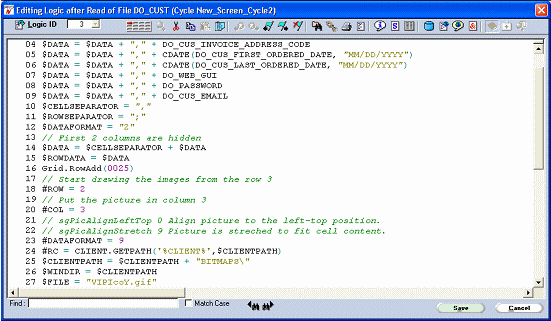
Fig 1 shows a typical logic in which the comments are highlighted in green. Comments may also be placed at the start of a line or after logic statements in a line by using ‘//’. Step blocks are defined in the form of ‘:1’ and are the only item permitted on a logic line when used.
Fig 1 A Typical Logic

The logic editor is invoked from logic event points within properties sheets, the event view or from the open logic toolbar option. Reassignment of a logic id is achieved by clicking the reassign icon, Fig 2, which will then permit the entry of a specific logic id, selection via a combo list or the generation of the next free logic by using the return key.
Fig 2
![]()
The icon will change when reassigning to that shown in Fig 3 and will also be shown when new logics are to be created by clicking on blank event points.
Fig 3
![]()
Validation of keywords and variables is performed on completion of each line and full block checks for complete ‘IF’ type statements are performed on logic completion. If the logic is in error it will be marked as such. If a function with logic errors is built a warning will be displayed.
If a logic line is invalid the ![]() symbol will appear next to the line in error. The toolbar options
symbol will appear next to the line in error. The toolbar options ![]() can be used to navigate forward and backward to errors within a logic. Clicking on this symbol will display the current errors (see Fig 8.4).
can be used to navigate forward and backward to errors within a logic. Clicking on this symbol will display the current errors (see Fig 8.4).
If logic is saved in an invalid form a ![]() symbol will appear at the top of the logic editor when the logic is next opened. Clicking on this symbol will display the current errors, Fig 4, and allow navigation to the logic line by selection of a line and clicking the goto .
symbol will appear at the top of the logic editor when the logic is next opened. Clicking on this symbol will display the current errors, Fig 4, and allow navigation to the logic line by selection of a line and clicking the goto .
Fig 4

Window assistance is provided on a logic line (F4 or right click) for search and retrieval of variables and scratch variables as well as object selection to be used in building set property statements. Scratch variables are prompted for definition when first used within logic.
The toolbar provides access to the clipboard search facility as well as more general function editor windows, such as interface maintenance.
The clipboard, which behaves in the same manner as the dynamics view, allows for the selection of individual lines or from/to selections via the selection pips. Once copied to the common clipboard this may then be selected and pasted at any time into any active logic edit sessions. A logic graphic indicates the availability of a logic fragment within the clip manager.
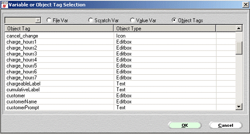
Another useful feature when editing logic is being able to select variables, objects and properties to append to a line. This feature may be accessed by right clicking (window key F4) on a logic line, which will popup a selection dialogue, Fig 5.
Fig 5

Clicking on an item will return it to the logic line.
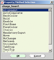
If as in the shown example an object tag in selected, it will be returned with a dot appended allowing further window access to the object’s supported properties, Fig 6.
Fig 6

Topic ID: 500217